| Chapter # | pages | source file | size |
|---|---|---|---|
| front cover | i-ii | TDR-F.doc | |
| ATLAS collaboration | iii-vi | TDR-Inst.doc | |
| Table of Content | vii-viii | TDR-TOC | |
| Chapter 1 | 1-3 | TDR-1.doc | |
| Chapter 2 | 4-8 | ||
| Chapter 3 | 9-34 | TDR-3.doc | |
| Chapter 4 | 35-45 | TDR-4.doc | |
| Chapter 5 | 46-47 | TDR-5.doc | |
| Chapter 6 | 48 | ||
| Chapter 7 | 49-50 | ||
| Chapter 8 | 51-58 | TDR-8.doc | |
| Chapter 9 | 59-78 | TDR-9.doc | |
| Chapter 10 | 79-80 | ||
| List of Figures | 81-84 | TDR-LOF | |
| List of Tables | 85 | TDR-LOT |
| fig.# | page | Figure caption | jpg | |||
|---|---|---|---|---|---|---|
| Front Cover | ||||||
| p. i | Whole view of solenoid | fig_cover.epsi | fig_cover.ps | Makida | ? | |
| Chapter 2 | ||||||
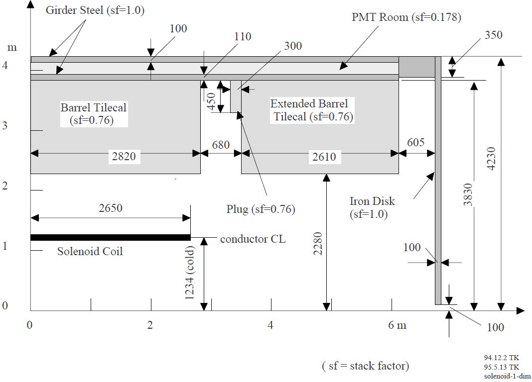
| Fig. 2-1 | p. 4 | Magnetic components of ......... | yoke.pdf | yoke.jpg | ||
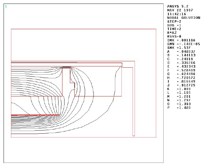
| Fig. 2-2 | p. 5 | The magnetic flux line......... | flux.pdf | flux.jpg | ||
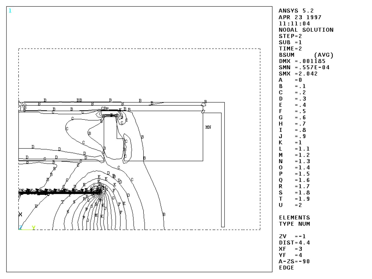
| Fig. 2-3 | p. 5 | Contour plot of the total......... | Bsum.pdf | Bsum.jpg | ||
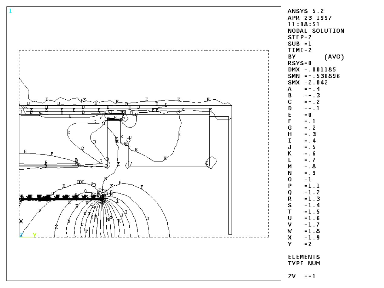
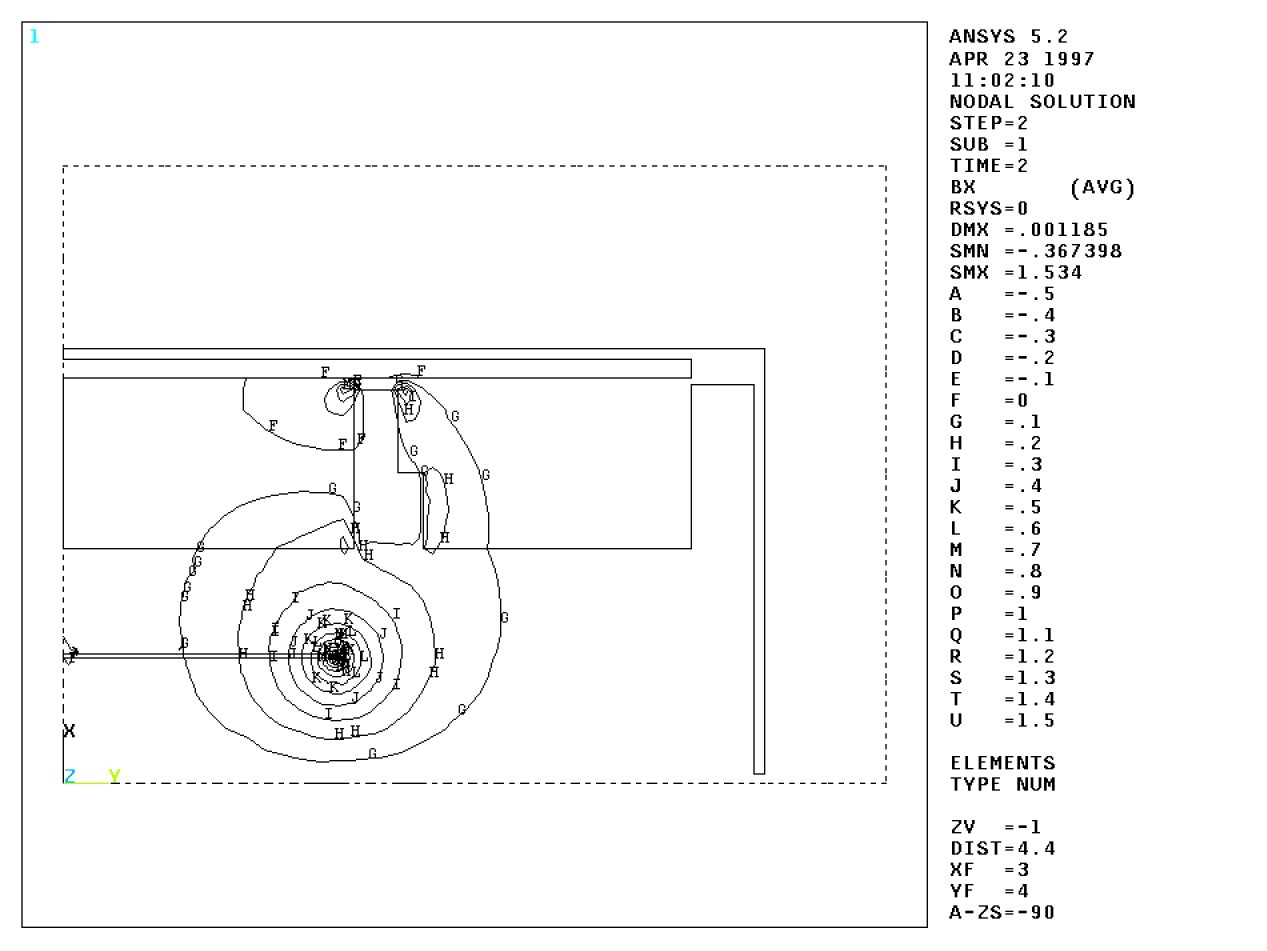
| Fig. 2-4 | p. 6 | Bz contour:......... | Bz.pdf | Bz.jpg | ||
| Fig. 2-5 | p. 6 | Br contour:......... | Br.pdf | Br.jpg | ||
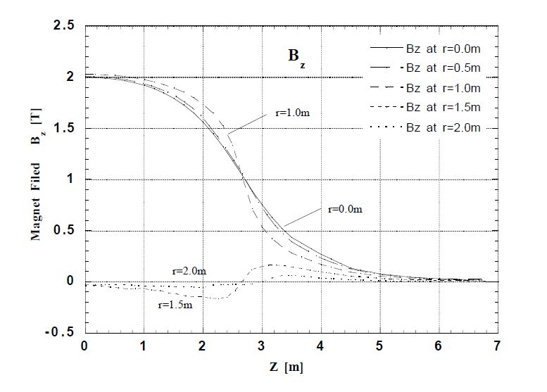
| Fig. 2-6 | p. 6 | Bz as a function of z. | bz-zdep.pdf | bz-zdep.jpg | ||
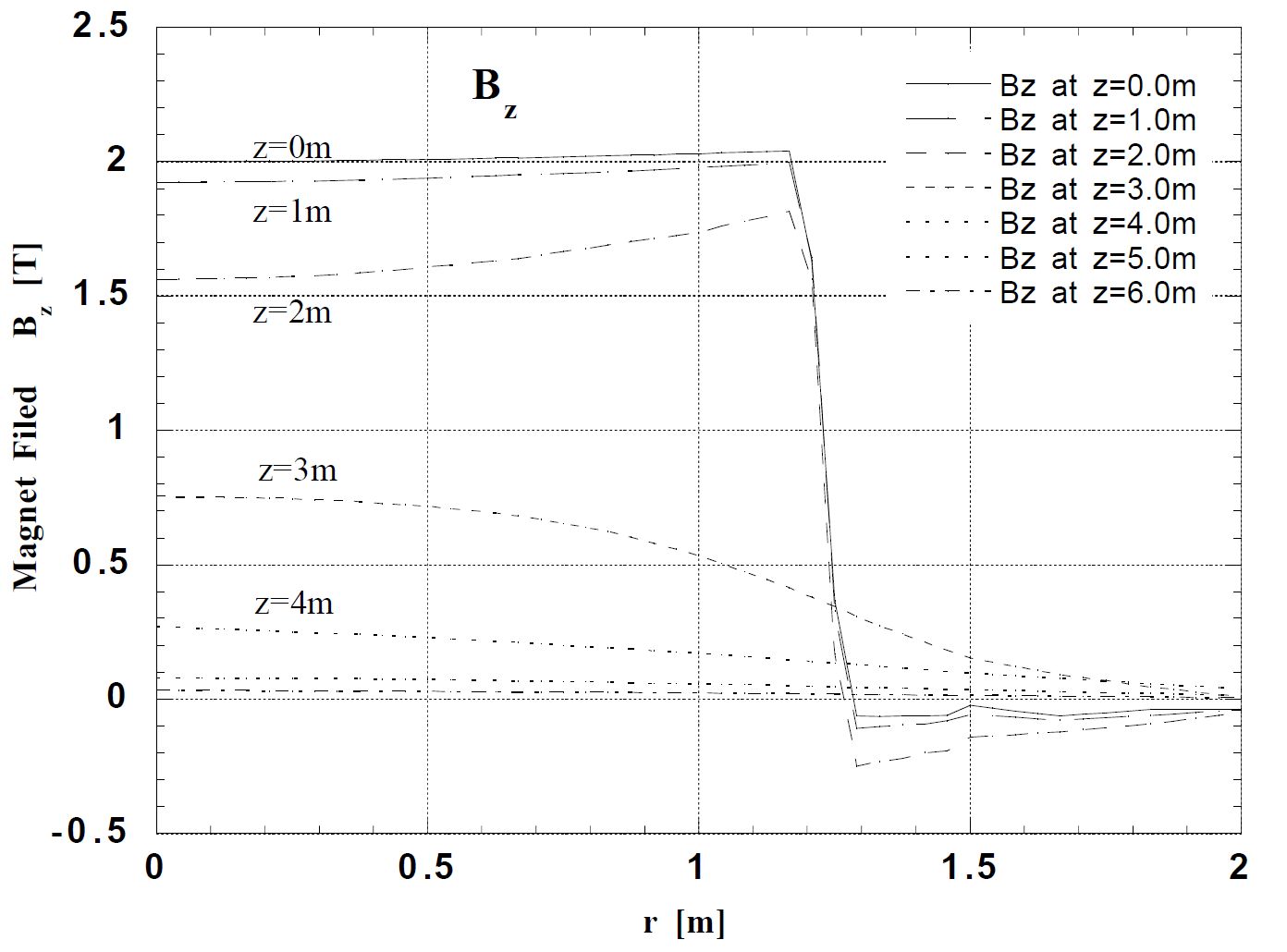
| Fig. 2-7 | p. 6 | Bz as a function of r. | bz-rdep.pdf | bz-rdep.jpg | ||
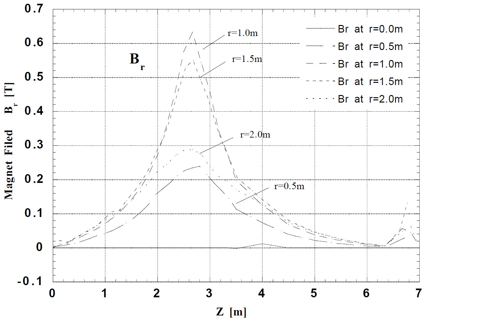
| Fig. 2-8 | p. 6 | Br as a function of z | br-zdep.pdf | br-zdep.jpg | ||
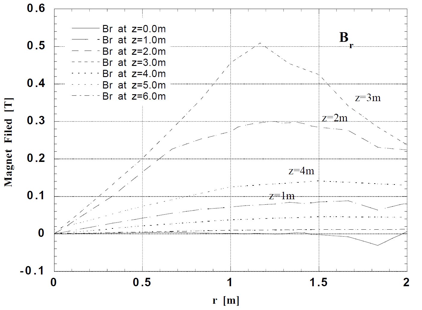
| Fig. 2-9 | p. 6 | Br as a function of r. | br-rdep.pdf | br-rdep.jpg | ||
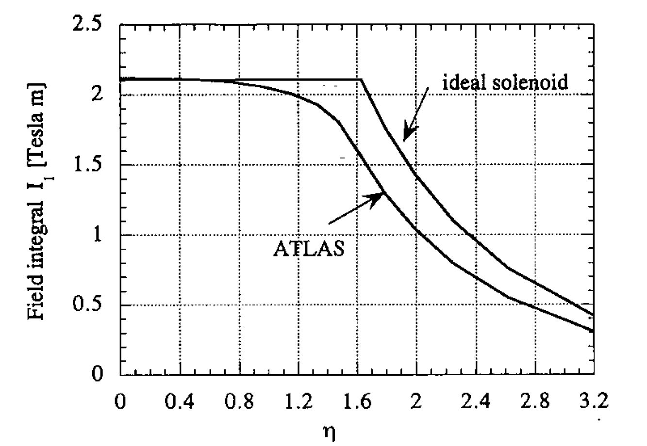
| Fig. 2-10 | p. 7 | Comparison of the .................. | field-int-i1.pdf | field-int-i1.jpg | ||
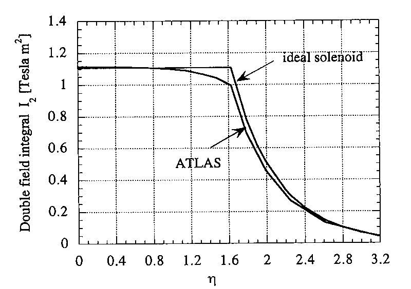
| Fig. 2-11 | p. 7 | Comparison of the ......... | field-int-i2.pdf | field-int-i2.jpg | ||
| Fig. 2-12 | p. 7 | Capability of momentum measu......... | field-int-ratio.pdf | field-int-ratio.jpg | ||
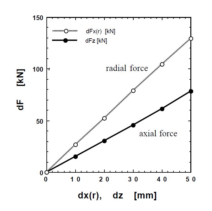
| Fig. 2-13 | p. 8 | Axial and radial decentering ......... | dec-force.pdf | dec-force.jpg | ||
| Chapter 3 | ||||||
| Fig. 3-1 | p. 10 | Enthalpy of aluminium as ......... | fig3-2.epsi | enthalpy.ps | Makida | |
| Fig. 3-2 | p. 11 | Plot of the stored energy ......... | em-ratio.eps | enthalpy.ps | Makida | |
| Fig. 3-3 | p. 13 | Cross section in the rz plane......... | fig3-4.epsi | |||
| Fig. 3-4 | p. 14 | Cross-section of the coil......... | rz-cross.eps | |||
| Fig. 3-5 | p. 15 | Cross-section of the ......... | rphi-cross.eps | |||
| Fig. 3-6 | p. 17 | Coil cross-section. | coil-Xsection.eps | |||
| Fig. 3-7 | p. 18 | Stress in the support cyl......... | stress.eps | |||
| Fig. 3-8 | p. 19 | Shear stress on the glue ......... | shear2.eps | |||
| Fig. 3-9 | p. 20 | Stress-strain curve of pure......... | stress-strain-1.pict | |||
| Fig. 3-10 | p. 20 | Stress-strain curve of ......... | ss-cruve.eps | |||
| Fig. 3-11 | p. 20 | Coil deformation due to ......... | deformation.epsi | |||
| Fig. 3-12 | p. 21 | Axial pure-Al strip ......... | alstrip.pict | |||
| Fig. 3-13 | p. 21 | Thermal conductivity ......... | thermal-cond.pict | |||
| Fig. 3-14 | p. 22 | Quench simulation ......... | fig3-14.epsi | |||
| Fig. 3-15 | p. 23 | Design of aluminium ......... | conductor.eps | conductor.ps | Kondo | MiniCad 6 |
| Fig. 3-16 | p. 24 | Short-sample character......... | IB.eps | |||
| Fig. 3-17 | p. 26 | Bonding structure at ......... | epoxy.eps | |||
| Fig. 3-18 | p. 26 | Cross section of the insul......... | gug-ug.eps | |||
| Fig. 3-19 | p. 27 | A schematic view of the ......... | triangle-3D.eps | |||
| Fig. 3-20 | p. 27 | Design of the triangle support. | drawing-triangle.epsi | |||
| Fig. 3-21 | p. 27 | FEA analysis of the coil cylinder......... | fig_all_load.epsi | |||
| Fig. 3-22 | p. 28 | Load distribution in each triangle | support-load.eps | |||
| Fig. 3-23 | p. 28 | (a) Displacement (left) and stress | fig_deform.epsi | |||
| Fig. 3-24 | p. 29 | A sketch of the LHe cooling pipe........ | fig_support_ana.epsi | |||
| Fig. 3-25 | p. 30 | Cross section of the end cryostat | cooling.eps | |||
| Fig. 3-26 | p. 31 | Cross section of the coil service | fig3-31.epsi | |||
| Fig. 3-27 | p. 31 | Supporting strut which is attached | fig3-32n.epsi | |||
| Fig. 3-28 | p. 32 | Rf view of the end-part in the | fig3-33.epsi | |||
| Fig. 3-29 | p. 32 | Chimney connection. | fig3-38.epsi | |||
| Fig. 3-30 | p. 33 | Chimney route through the | fig3-35n.epsi | |||
| Fig. 3-31 | p. 34 | Thermal contraction of chimney. | chimney-motion.eps | |||
| Fig. 3-32 | p. 34 | Pressure drop in the transfer | He-pressure.eps | |||
| Chapter 4 | ||||||
| Fig. 4-1 | p. 36 | ATLAS refrigeration and distri | cryo-system.eps | |||
| Fig. 4-2 | p. 37 | Flow schematic of the cryogenic | doi-flow.eps | |||
| Fig. 4-3 | p. 38 | Parameters and schematic picture | dewar.pict | |||
| Fig. 4-4 | p. 38 | T(Temperature)-S(Entropy) | TS-diagram.eps | |||
| Fig. 4-5 | p. 40 | Flow diagrams during (a) pre-cooling | doi-3-mode.eps | |||
| Table 4-4 | p. 41 | Operational modes fot the ATLAS | valve.eps | |||
| Fig. 4-6 | p. 42 | Cooling path model. | cooling-path-model.eps | |||
| Fig. 4-7 | p. 43 | Pressure profile during cool down. | p-all.eps | |||
| Fig. 4-8 | p. 44 | Calculated results of two-phase | p-x-m.eps | |||
| Fig. 4-9 | p. 45 | Thermosyphon model. | cooling-path-model-2.eps | |||
| Fig. 4-10 | p. 45 | Solenoid cooling pipe model for | siphon-cooling-pipe.eps | |||
| Chapter 5 | ||||||
| Fig. 5-1 | p. 46 | Diagram of the electrical system | power-circuit.eps | |||
| Chapter 7 | ||||||
| Fig. 7-1 | p. 50 | Electrical and thermal ......... | he-stop.eps | |||
| Chapter 8 | ||||||
| Fig. 8-1 | p. 51 | Major schedule of construction, ..... | schedule.eps | |||
| Fig. 8-2 | p. 53 | Flow diagram of the Solenoid ......... | fabrication-flow.eps | |||
| Fig. 8-3 | p. 55 | Work of connections of the ......... | fig8-5-1.epsi | |||
| Fig. 8-4 | p. 55 | Sketch of the surface test setup. | fig_grand_test.epsi | |||
| Fig. 8-5 | p. 56 | A sketch how to install the ......... | install.eps | |||
| Fig. 8-6 | p. 57 | R-phi cross section of the ......... | AT720013PL.EPS | |||
| Fig. 8-7 | p. 57 | Cryogenic elements in the ......... | AT720052PL.EPS | |||
| Fig. 8-8 | p. 58 | Utility area for the magnet ......... . | usa-15.eps | |||
| Fig. 8-9 | p. 58 | A view of the power supply ......... | power-supply.eps | |||
| Chapter 9 | ||||||
| Fig. 9-1 | p. 60 | Dependence of RRR on the ......... | ppm.eps | |||
| Fig. 9-2 | p. 60 | Dependence of yield strength......... | cold-work.eps | |||
| Fig. 9-3 | p. 60 | RRR as a function of yield ......... | ys-rrr-znsi.eps | |||
| Fig. 9-4 | p. 61 | Cross section of the SDC ......... | conductor.pict | |||
| Fig. 9-5 | p. 61 | Mechanical characteristics ......... | ys-9-5.eps | |||
| Fig. 9-6 | p. 61 | Expected yield strength at ......... | zn-x.eps | |||
| Fig. 9-7 | p. 63 | Picture of the coil and electrical......... | photo_SDC_coil_cross.pict | |||
| Fig. 9-8 | p. 63 | Shear strength test set up .... | shear-test-setup.eps | |||
| Fig. 9-9 | p. 63 | Shear strength of GFRP .... | sdc-shear.eps | |||
| Fig. 9-10 | p. 63 | Shear strength of GUG .... | atlas-shear.eps | |||
| Fig. 9-11 | p. 63 | Tensile strength measur.... | gug-test-ral.eps | |||
| Fig. 9-12 | p. 64 | Shear strength of GUG bonding.... | atlas-winding-shear.eps | |||
| Fig. 9-13 | p. 64 | Picture of the sample for .... | triangle_sample.pict | |||
| Fig. 9-14 | p. 64 | Sketch of the machine for.... | triangle-setup.eps | |||
| Fig. 9-15 | p. 64 | Test result of the support...... | support_test.epsi | |||
| Fig. 9-16 | p. 66 | Isometric view of the proto..... | 3D.pict | |||
| Fig. 9-17 | p. 66 | Cross section of the axial ..... | fig9_17.pict | |||
| Fig. 9-18 | p. 66 | Machine for internal winding. | wind-machine-1.pict | |||
| Fig.9-19L | p. 67 | Photographs of the coil ..... | winding_top.pict | |||
| Fig.9-19R | p. 67 | Photographs of the coil ..... | winding_guide.pict | |||
| Fig. 9-20 | p. 68 | The SDC prototype coill ..... | SDC_coil.pict | |||
| Fig. 9-21 | p. 68 | The isogrid outer vacuum ..... | isogrid.pict | |||
| Fig. 9-22 | p. 69 | The SDC prototype solenoid ..... | solenoid.pict | |||
| Fig. 9-23 | p. 69 | Set-up of the prototype ..... | fig9-22(a).eps | |||
| Fig. 9-24 | p. 69 | The cool-down curve of the test. | cooldown.epsi | |||
| Fig. 9-25 | p. 70 | Pressure drop in the single..... | fig9-22(b).eps | |||
| Fig. 9-26 | p. 70 | Quality factor along the ..... | fig9-23.eps | |||
| Fig. 9-27 | p. 71 | Summary of the exciation test. | sdc-excitation.eps | |||
| Fig. 9-28 | p. 71 | Operating load line of the SDC ..... | sdc-ib.eps | |||
| Fig. 9-29 | p. 72 | Mechanical stress/strain ..... | sdc-s-i2.eps | |||
| Fig. 9-30 | p. 72 | Stress balance in supercond..... | sdc-ss.eps | |||
| Fig. 9-31 | p. 72 | Measurement of temperature..... | sdc-he-stop.eps | |||
| Fig. 9-32 | p. 72 | Fast ramping effect on the ..... | ramp.eps | |||
| Fig. 9-33 | p. 73 | Quench energy measurement ..... | mqe.eps | |||
| Fig. 9-34 | p. 74 | Time profile of the coil ..... | q-11600.eps | |||
| Fig. 9-35 | p. 74 | Current dependence of coil ..... | quench-tmax.eps | |||
| Fig. 9-36 | p. 75 | Distribution of the temperature..... | sdc-t-dist.eps | |||
| Fig. 9-37 | p. 75 | Current discharge w/o quench ..... | slow-discharge.eps | |||
| Fig. 9-38 | p. 76 | Coil temperatures during the ..... | warm-up.eps | |||
| Fig. 9-39 | p. 76 | Comparison of ramp rate ..... | ramp-compare.eps | |||